| 1 |
|
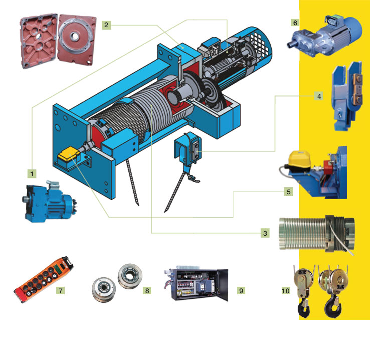
LIFTING MOTOR |
| |
|
The hoist has a cylindrical short circuit motor with an incorporated electromagnetic brake.
The motor and brake have been designed for continuos service with high duty factors and cycles.
The brakes are electromagnetic disc, with asbestos free flat faced linings. They offer great reliability and automatic braking in the event of power failure. The friction linings are long lasting and the brake is easy to regulate.
Protection IP-55 to DIN 40050.
The standard version motor has the option of one or two speeds. The second speed has a relation of 1/6. Other relations 1/2, 1/3, 1/4 are available by customer request. Also upon customer request, we can supply inverter control or slip-ring motors. |
| |
|
|
| 2 |
|
GEARBOX |
| |
|
Robust and compact, situated on the exterior, allowing ease of access.
The helical teeth in all the gears are cut with great precision, in cemented steel, assuring silent running, great reliabilty and long life.
The drive from the motor to the gearbox is direct, avoiding coupling devices which have a tendancy to fail.
All of the gears are lubricated by an oil bath in the interior of a closed casing, machining of the gear locations is made by high precision machine tools. |
| |
|
|
| 3 |
|
DRUM & ROPE GUIDE |
| |
|
The drum is designed end manufactured according to FEM 966 standard.
Constructed from a seamless steel tube with grooves machined according to DIN 15061. The groove is machined dependent on the wire rope exits i.e.1 or 2 exits.
The drum is fitted to the hoist frame using high quality, self lubricating. comercial bearings. The drive from the gearbox to the drum is via a direct splined shaft.
The rope guide is manufactured from GGG70 nodular cast iron with self lubricating graphite, which also gives particular resistance to wear.
The rope guide is formed by two pieces, which can easily be assembled without special tools. |
| |
|
|
| 4 |
|
OVERLOAD LIMIT DEVICE |
| |
|
All of our hoists are fitted with an electro mechanical load cell as standard (electronic control).
This load cell consists mainly of 2 parts:
- A electronic cell pin
- Load cell unit (to be installed in the electric panel). |
| |
|
SECURITY LIMIT SWITCH |
| |
|
All of our hoists are fitted with a security limit switch in lifting, preventing a possible failure of the main limit switch. |
| |
|
|
| 5 |
|
LIMIT SWITCH |
| |
|
Is located in the drum axle. It limits hook movement in the up and down motions. |
| |
|
|
| 6 |
|
TRAVELLING GEAREDMOTORS |
| |
|
Are specially designed for crane application. Low torque high inertia drives, provide gradual acceleration and smooth deceleration without excessive swing.
The drive to the wheel is via a direct splined shaft. |
| |
|
|
| 7 |
|
PUSH BUTTON PENDANT |
| |
|
Is manufactured from high impact polypropylene and provides double insulation. The various motions are controlled by pushbuttons which are colour coded as well as being indentified by internationally recognised symbols. Low dead weight and ergonomically styled housing reduces operator's fatigue. |
| |
|
|
| 8 |
|
WHEELS |
| |
|
Dependant on the hoist model, the wheel material can be GG 60 for monorail hoists and GGG 70 (nodular cast iron with graphite structure) for birrail crabs. As shown, drive is via a direct splined axle. |
| |
|
|
| 9 |
|
ELECTRICAL CABINET |
| |
|
A metallic box located on the hoist frame, allowing easy access to the electrical control components. |
| |
|
|
| 10 |
|
BOTTOM HOOK BLOCK |
| |
|
The sheaves are designed according to FEM 9661. The machining of the groove is made according to DIN 15061. The cross pin and nut are machined according to DIN 15412 & 15413.
The hooks are selected according to DIN 154000 and machined to DIN 15401 & 15402, depending on whether they are single or double. |